UTILITY LINES AND FACILITY MANAGEMENT - A TASK FOR THE SURVEYING ENGINEERProf. Lothar GRÜNDIG and Dr.-Ing. Frank GIELSDORF, GermanyKey words: Facility Management, GIS, documentation, Service lines. ABSTRACTThis paper deals with the specific tasks common to linear objects and facility management systems relevant for surveying engineers. The need for documenting their data using modern geographic information systems (GIS) technologies is accepted without question for energy providers, communication providers, and for traffic systems of roads and rails. All gas, electricity and water suppliers are required to document the geometrical position of the utility lines constituting their respective networks. Facility management can be seen as a consequent extension of the methods of managing company resources for utility lines into the building sector. Therefore the basic tasks are similar, especially proper spatial data acquisition for buildings and the interface to computer aided facility management systems are required. The type of work and the specific requirements for these subjects will be specified and analyzed. INTRODUCTIONThe documentation of the geometrical position for gas, electricity and water suppliers is usually achieved by sketching the various house connections on a large scale map based on cadastral data. The providers need to maintain their networks permanently in order to make best use of it. In areas of application where geometric information of large scale has to be maintained, the data for documenting the as built situation have a proportion of 80% of the whole GIS investment, and these data normally survive several hard- and software generations. Many enterprises in the area of providing services for energy or getting rid of the waste are in the process of changing over to net information systems, or they already make best use of it within their enterprise. The cost for generating such a complex information system might be considerable, as especially the tasks of management and maintenance of the system have to be modelled thoroughly. In addition, the engineering design demands become much larger, and more complicated as traffic and population are growing. This results in plans which are significantly more complicated, as is the task of monitoring and proper maintenance of linear objects after they are built. The requirement of a reliable data management of sensitive geometrical data can be outlined taking the example of rails for modern high speed trains or for municipal rail systems. The example of rails is also a representative demonstration of the synthesis of high precision and reliable geometric information which is closely connected with descriptive information. In order to make best economic use of all resources, of landed property, including buildings, and all relevant parts and processes involved, a growing number of enterprises put effort in facility management. It becomes more and more obvious that 80% of the cost caused by a building during its life cycle will be spent for the usage of the building. The cost are due to the interest rate to be paid, any changes of usage, the repair work, the insurance, the taxation, the rental costs, the energy and the cleaning. The original financial effort for establishing the building only sums up to 20%. BASICS OF FACILITY MANAGEMENTFacility Management (FM) is the management concept for planning, for the use and the best economic administration of landed property and buildings, including the associated resources of personal and relevant objects. FM is based on the principle of an integrated complete management of all relevant data taking into account its whole life cycle, thus providing transparency of information for all institutions involved in the decision making process.
Figure 1: columns of FM Comparing the basic principles of FM with the establishment and use of a documentation system for the resources of service providers of linear objects like utility lines, gas and electrical lines, etc., it becomes obvious that both tasks are very similar in their basic requirements and structure. In fact FM can be seen as the consequent extension of the methods, used so far for management of linear objects, to the management of buildings (fig.:2). For this task it is required that appropriate data structures and tools for supporting the usage and the maintenance are designed, evaluated and made available to. In addition, extended data acquisition techniques and tools for the setting up data and data exchange, for providing the respective views and the analysis of all the data needed for facility management are required.
Figure 2: Global view of FM (Runne, 2000) In general the data of FM must be interconnected properly applying a unique reference frame in order to guarantee data consistency. Due to the huge amount of information which has to be managed within FM the tasks of FM can only be fulfilled economically with suitable information systems. SPECIFIC PROPERTIES OF FACILITY MANAGEMENTComputer Aided Facility Management Systems (CAFMS) map and manage all cost relevant processes of landed property and buildings. In order to find a suitable mapping, the processes have to be analyzed. Two main classes of information result. There is the class of object information dealing with object specific properties, and the geometry related information. In general the geometry related information forms the skeleton where all information, related to the property of objects, can be referenced to. Analyzing the effort necessary to generate and maintain a CAFMS, it becomes obvious that the part of data acquisition and consistent update of geometrical information causes immense cost. Therefore every user of a CAFMS has a fundamental interest in minimizing this high economic effort, taking into account the boundary condition that the necessary quality will just be maintained. The surveying engineer has shown best skills in finding the way to the basic parameters for an economic acquisition of geometrical data with acceptable information quality. In two areas of activity, where the experience in proper handling geometrical data is essential, the surveying engineer can contribute to the solution. These are the design of suitable data models for the task described before, and the data acquisition task for geometrical data, where not only the actual measurements are considered, but the automated processing of geometrical information of all types. Both areas will be illustrated in a more detailed way. Development of appropriate data modelsThe data models of existing CAFMS monitor the way they were designed in the past. Historically at the first systems on the market, geometry information was dealt with only via geometrical attributes to the objects described in the systems. Development of data models involved property related data to the relevant objects of the system, and just added geometrical information as additional attributes to these objects. The specific properties of geometrical information were not considered at all. Therefore the data often have been redundant and susceptible to anomalies or blunders during the update phases of the data. In a simplified way, the process of design for these systems can be described as follows: Property Related Information ® Geometry ® Data Model It became apparent that geometry information have to be treated as a specific class of information with it own rules. Geometry information forms the reference frame for all descriptive information of the objects properties. This level of knowledge has to be applied during the process of development of data models. At the beginning of the design process an answer to the following question has to be found: How can the geometrical reference, for the property related information, be mapped to the data model in a most flexible way? Geometry ® Property Related Information ® Data Model Therefore the professional expertise of the surveying engineer is already required during the conceptual phase of a CAFMS. During the conceptual process a number of questions must be answered and taken care of:
It is a prerequisite for an optimal result to answer these questions in an acceptable way. Only then the economical effort will be minimized while the geometrical quality of the data in the CAFMS will be preserved. Data Acquisition and ProcessingThe acquisition of geometrical data usually is done via digitization of available maps, or if these data are not available or out of date, via local measurements on site. Especially for gathering the local measurements on site, geodetic methods, like tachometry, close range photogrammetry or laser scanning, are applied. This results in the best geometrical quality, it requires, however, an enormous financial effort. It is this effort which stops potential users from establishing a powerful CAFMS including geometry. In order to arrive at an economic solution it will be necessary to move the intelligence from the data acquisition methods applied on site to the data processing procedure. Primarily, the task of the surveying engineer should not be, to perform the measurement on site. These measurements should be gathered from personal of low professional level applying robust and simple to handle tools, like measurement tapes or hand hold laser distance measurement instruments. The result of this way of data acquisition are redundant measurements which are expected to show a large rate of errors. The task of the surveying engineer will be to find a consistent result, removing these errors while transforming the data into a unique spatial reference frame. This task is a typical application of geodetic adjustment techniques, the surveying engineer is used to. SPECIFIC PROPERTIES OF DIFFERENT CLASSES OF LINEAR OBJECTSGeographic information systems for railways cover the areas of system planning and design, as well as the task of information retrieval for maintenance, use and archiving. Traffic systems like roads and rail information systems are based on the steps of planning and design which are subject to a large number of rules and prescriptions. An alignment is a one dimensional representation of a roadway or a railway. The process of finding the proper alignment includes the determination of the geometrical parameters of the alignment. The information necessary for documentation and operation can be classified in
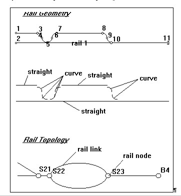
The geometrical information describes the alignment curve and its relation to the respective objects in space. The global spatial connection is defined by points with coordinates x,y,z. The parameters of the individual alignment parameters locally describe the geometrical properties of the element in consideration. The relations between the global reference frame and the local geometry are defined mathematically. Topological information is needed if a net structure is created by a group of linear objects (rail or road network). For the topological modelling the net structure can be described as a graph, i.e. a group of nodes is connected by a group of links. The topological information can be derived by abstraction from the geometrical information. In this process the clearly defined geometry is neglected preserving only the inter-connectivity inherent in the geometrical description.
Figure 3: Relations between rail geometry and rail topology (Gründig, Bahndorf, Gielsdorf 1993) Figure 3 demonstrates the relationship between the topological and geometrical information. Any rail geometry may be modelled topologically in the above described way. The inverse task is, however, non-uniquely defined, since it is possible for multiple rail geometry to be modelled with exactly the same topology. The resulting frame of nodes and links can successively serve as logical base for the object description which is the third source of information. Typical descriptive data of relevant objects for users are:
Geometrical and topological objects can both serve as a basis for the object description. The fact that geometrical objects build the base of all additional information documents the fundamental relevance of any kind of documentation for linear objects. In the traditional way maps and plans are used for documentation. The geometrical objects are projected into the x,y-plane, applying a proper scale and are presented on paper. The height information is either given by numbers or contour lines or by specific plans. The respective scale depends on the usage of the plan. Object descriptive information in analogue plan has either been presented by symbols (types of lines, types of points, hatching) or via an appropriate legend. The plans used can be classified by content, scale and matter of use.
Table -1 maps and plans A characteristic documentation of linear objects are the presentations of geometrical information in diagrams. Typical examples of such diagrams are longitudinal profiles, cross sections plans, as well as curvature plans or rail documentation plans. The way of presentation can be characterised by visualising the relevant spatial information as one-dimensional coordinate along a line of reference - the alignment curve -. Typical representations for rails are height, super-elevation, and curvature. Another form of representation are lists which are used as the alphanumeric way of analogue documentation. Information on geometry is often stored in lists of coordinates. Mains and utility lines are linear objects with similar properties. According to the type and kind of the product to be transported a large number of rules apply for planning, construction, and operation. The basic for this task is a reliable, consistent, and actual documentation of each individual part and for the whole service network. This implies that the lines must be based on a unique spatial reference in connection with all other infra-structural data. The essential information is not only the specific property of the type of mains relevant for making best use of it but the influence of the use on other service lines or third parties. Especially the question of emergency cases is important which can be caused by the use of and to which extent. This implies that the mains and service lines should be managed based on a unique spatial reference frame. The descriptive data of the objects can be mapped on information systems in the same way as described above for rails and roads. The shortcomings of existing documentation systems often are their inflexibility in providing the documentation information for third parties, and in preserving the actuality of the geometrical data. The direct field access to the information system from the actual line to be monitored using measurement techniques for determining the spatial relations, and tools provided for management and update are essential means to preserve the actuality of the documentation.
Figure 4: Excerpt from the documentation of GASAG AG Berlin (Lörke, Schwermer 1997) The central question for the management of geometrical information for linear objects is: In which system will they be geo-referenced . Generally two options exist:
In many systems the first option has been applied. The attempt was made to copy the traditional analogue point of view directly to the data model. The two-dimensional coordinates of objects will be calculated temporarily for the purpose of the graphical presentation on screen or in maps. However, this solution leads to problems, if the geometry of the reference line undergoes geometrical changes, i.e. during maintenance or repair work of a track. In this case anomalies of change may result, because of the one-dimensional coordinates of all objects coming after the place of repair, they will not be valid any more. The second way will be more favourable. It is assumed however that the transformation rules between the one-dimensional reference system of the linear object and the global two or three dimensional global reference system is known. In this case all coordinates are independent of changes of geometry of a reference line. The one-dimensional coordinates will be generated temporarily for the graphical presentation in diagrams. TASKS COMMON TO LINEAR OBJECTS AND FACILITY MANAGEMENTTasks common to linear objects and facility management cover the following topics:
Special emphasis has to be given to the management and usage. The traffic provider road, rail air and water for instance historically have undergone unimodal developments. Optimisations of the traffic systems were done within the respective system. The digital rail maps of German Rail and of other European Rail Companies have developed independently from the activities of the digital road maps. The specifications are not compatible to those of the road data bases which are available throughout Europe. The main problem of the data acquisition of digital maps is the preservation of quality for all steps from the data acquisition down to the data management and use of data. One main cost factor is the topologically correct modelling of the traffic relations (Möhlenbrink 1994). The change from one transport system to the other becomes difficult as the modelling of nodes of transfer has not adequately been realised. A key role is played by the provision of standardised views of the traffic networks. Only if digital road maps and rail maps will be available in a unified information structure the traffic and transport management achieves practicability. A main problem still is the consistent maintenance management of the geometrical data and their interdependent objects in order to guaranty the actuality of the data. The usage of information makes it necessary to extract data according to specific tasks, and to visualise the result. Of special importance are presentations of the spatial geometrical objects and their relations. The change of scale often requires a generalisation of the geometrical data which can only be realised by creating a new geometry of the objects to be presented. In GIS, where the interrelation of graphical and alphanumeric data are modelled, several geometrical representations could be assigned to the same object. These representations can be based on the scale for presenting it in the appropriate way. Especially for technical documentation, the details with small spatial extension could be of special importance. In sketches of detailed objects only some objects will be affected. Modifications of the objects, not of the geometry, which are made in the detailed sketches, automatically modify the object in all other presentations, as the objects are already known to the information system but with a different geometrical representation. Synthetic mapping systems together with database technology could speed up work processes for data acquisition and update for gas, electricity and water suppliers. It would not be necessary to sketch a situation individually but to identify and mark the synthetic typical images (Scheu 1996). CONCLUSIONThe high demand both for personal mobility and for the ability to transport goods of all kinds over long distances is characteristic for our time. It is necessary to dynamically balance traffic flow, to select the optimal routes for transport to provide drivers with a set of information services like optimal routes, traffic jams, road obstacles and to increase the efficiency of our transport system by integrating it in the best possible way. A key to all these problems is the information based on the geometry and topology of linear objects. The goal is approached by evaluating and documenting the typical representatives of linear objects with respect to the above mentioned characteristics. A key role for linear object type problems is the provision of standardised representations of traffic networks and of service and energy supply networks. When digital road- and rail maps will be available in a unique information structure intermodal traffic- and transport-management will become feasible. Common to facility management and linear objects is the modelling of geometry objects in a unique spatial reference frame which is independent of geometrical changes of any reference object. It is essential to shift intelligence from the data acquisition tools to the processing part, exploiting redundancy of measurements and applying powerful adjustment techniques in data processing. In addition, different levels of generalisation have to be realised in the data model for geometrical objects which should be based on a common data pool. LITERATURE
BIOGRAPHICAL NOTESProf. Dr.-Ing. Lothar Gründig, graduated Dipl.-Ing. in Geodesy 1970, 1975 Dr.-Ing, 1987 habilitation at Stuttgart University. Since 1988 Professor of Geodesy, Adjustment and Engineering Surveying at the Technical University of Berlin. Dr.-Ing. Frank Gielsdorf, graduated Dipl.-Ing. in Geodesy 1987 from the Technical University of Dresden, graduated 1997 Dr.-Ing. at the Technical University of Berlin, since 1997 post doctoral scientist at the Technical University of Berlin. CONTACTProf. Dr.-Ing. Lothar Gründig and Dr.-Ing. Frank Gielsdorf 18 January 2001 This page is maintained by the FIG Office. Last revised on 15-03-16. |