Article of the Month -
March 2013
|
Land Administration Standardization with focus on Evidence from the
Field and Processing of Field Observations
Peter VAN OOSTEROM, Christiaan LEMMEN and Harry
UITERMARK,
The Netherlands
1) The 'Land Administration
Domain Model (LADM)' was approved as an official International ISO
Standard a on 1 November 2012, a milestone for FIG. The proposal for
this standard was submitted by FIG to ISO almost five years ago. LADM
defines terminology for land administration, based on various national
and international systems that is as simple as possible in order to be
useful in practice. LADM covers the compete domain, surveying
included.It is highly relevant that documented field surveys can be
included, in combination with reconstructable adjustments to the spatial
database.
Key words: LADM, Surveying, data model
SUMMARY
This paper will focus on (cadastral) geodata acquisition, based on
field surveys in the context of the ISO 19152 Draft International
Standard (DIS) Land Administration Domain Model (LADM). During the
development of LADM existing standards have been re-used as far as
possible. Original observations related to adjudication, and all geodata
maintenance, because of land transactions, physical planning,
establishment of mortgage, etc. need to be documented. This is for
quality, consistency and integrity reasons. The documentation is the
basis for authenticity of the administrative and geodata. In case of
cadastral geodata this documentation is often referred to as "evidence
from the field".Data acquisition can be based on variety of approaches
(low cost / high tech), which not always involves conventional
terrestrial surveying. Observations may require transformations and
adjustments, or other corrections (e.g. rectangulation), before the
cadastral geodata for spatial units can be edited. Those transformations
and adjustments can be documented again. All different types of the
geodata acquisition can be represented in LADM. However, procedures for
data acquisition itself are not included in the standard.d.
1. INTRODUCTION
In the process towards the inclusion of Land Administration
information within the geo-information infrastructure, or in more
popular terms: the Geoweb, standardization forms a basic condition. Land
Administration information is a key element in the geo-information
infrastructure (Geoweb), and strongly related to other registrations.
The LADM has been submitted to ISO/TC211 (Geographic information), for
formal standardization and integration with other ISO/TC211
geo-information standards, such as ISO/IS 19107 Spatial Schema, ISO/IS
19108 Temporal Schema, ISO/IS 19111 Referencing by Coordinates, ISO/IS
19115 Metadata, and ISO/DIS 19156 Observations and Measurements (O&M).
The LADM has currently the status of a Final Draft International
Standard (ISO/DIS 19152) and was distributed in March 2012 by the
central ISO secretariat for a three month voting time period (ISO,
2011).
This paper is focusing on the Surveying and Spatial representation
sub-package of the LADM. First we will introduce the LADM into more
detail in Section 2. In Section 3 attention will be given to the
possible representation of spatial units into LADM. Section 4 gives a
short overview of the imported model ingredients/functionality from
other ISO standards. Cadastral Mapping is the issue of attention in
Section 5. The flexibility of the LADM is further demonstrated in a more
elaborate case described in Section 6. Finally conclusions are presented
in Section 7.
2. THE LAND ADMINISTRATION DOMAIN MODEL
Many LADM classes are subclasses of the superclass VersionedObject.
Class Versioned-Object is introduced in LADM to manage and maintain
historical and quality data for the complete contents of the database
developed based on the LADM. Management of historical data requires,
that inserted and superseded data, are given a time-stamp. See Figure 1.
Apart from the inclusion of management of history and quality for the
complete database, also source documents can be included. In principle
the updating of the database is based on authentic source documents –
which can not be changed. Class LA_Source has as attributes submission
(the date of submission of the source by a party); acceptance (the date
of force of law of the source by an authority); and recordation (the
date of registration – recordation – of the source by the registering
authority); extArchiveID for identification of documents in external
archives; lifeSpanStamp (history management –the moment that the event,
represented by the instance of LA_Source, is further processed in the LA
system (this is the moment of endLifespanVersion of old instances, and
the moment of beginLifespanVersion of new instances of related objects
in the database such as LA_Party, LA_RRR, LA_BAUnit and LA_SpatialUnit;
see below for an explanation of these classes); this is the “database
time”, compare the time stamps in LA_VersionedObject); sourceIdentifier;
mainType (the type of document according to ISO 19115); see Figure 2.
The abstract class LA_Source has two specializations:
LA_AdministrativeSource and LA_SpatialSource.
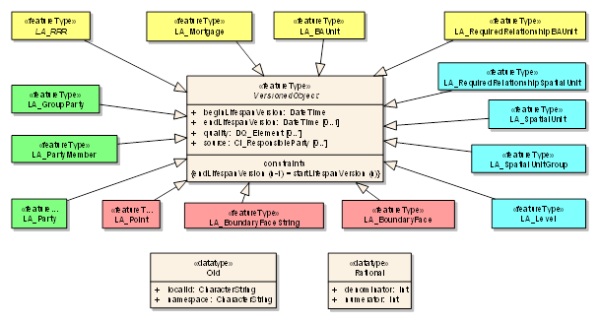
Figure 1. LADM Classes Versioned Object with subclasses
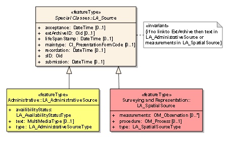
Figure 2. LADM Class LA_Source (wth subclasses)
The conceptual schema of the LADM is organized into three packages
(ISO, 2011): 1. Parties; 2. Basic administrative units, rights,
restrictions and responsibilities; and 3. Spatial units. The last
package includes the surveying and representation subpackage.
The main class of the Party Package is class LA_Party with its
specialization LA_GroupParty. There is an optional association class
LA_PartyMember (Figure 3). Parties are natural or non natural persons,
or groups of persons, or juridical persons, that compose an identifiable
single (legal) entity. A “group party” is any number of parties, forming
together a distinct entity; e.g. a village community or a tribe. Types
of LA_Parties can be extended by CodeList LA_PartyType.
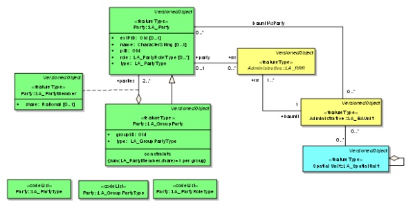
Figure 3. LADM Party Package and associations to other basic classes
The Administrative Package concerns the abstract class LA_RRR, with
its three subclasses LA_Right, LA_Restriction, and LA_Responsibility,
and class LA_BAUnit (Basic Administrative Units), see Figure 4. A
“right” is a action, activity or class of actions that a system
participant may perform on or using an associated resource. A
“restriction” is a formal or informal entitlement to refrain from doing
something. A “responsibility” is a formal or informal obligation to do
something. A “baunit” (an abbreviation for “basic administrative unit”)
is an administrative entity consisting of zero or more spatial units
(parcels) against which (one or more) rights (e.g. an ownership right or
a land use right), responsibilities or restrictions are associated, as
included in a Land Administration system. An example of a “baunit” is a
basic property unit with three spatial units (e.g. an apartment, a
garage and a rural parcel). It should be observed in relation to this
that rights, restrictions, and responsibilities may affect only a part
of the spatial unit, with the geometric representation of that part
missing. A “baunit” can be a group of spatial units under a zoning plan,
which is under development. Or, a group of spatial units as basis for
taxation. A basis for taxation can be more than property in case lease
is included: so a “baunit” for taxation is not necessarily the same as a
group of spatial units forming a property.
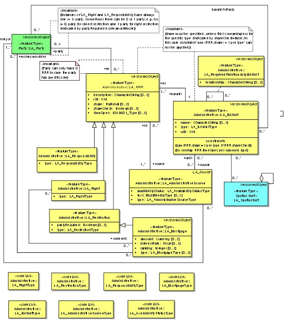
Figure 4. LADM Administrative Package with associations to
other basic classes
2.1 Spatial Unit Package
The Spatial Unit Package is most relevant given the focus of this paper.
This package concerns the classes LA_SpatialUnit, LA_SpatialUnitGroup,
LA_Level, LA_Legal¬Space¬Network, LA_LegalSpaceBuildingUnit, and
LA_RequiredRelationshipSpatialUnit (Figure 5). A “spatial unit” is a
point (or, multi-point), a line (or, multi-line), representing a single
area (or, multiple areas) of land (or water) or, more specifically, a
single volume of space (or, multiple volumes of space). Single areas are
the general case and multiple areas the exception.
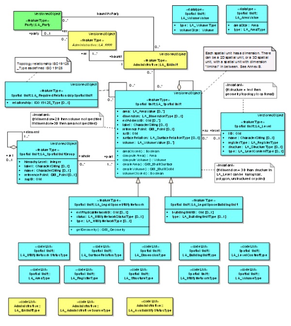
Figure 5. LADM Spatial Unit
Package with associations to other basic classes
Spatial units are structured in a way to support the creation and
management of basic administrative units. The Spatial Unit Package has
one Surveying and Spatial Representation Subpackage (See Figure 6), with
classes such as: LA_Point, LA_BoundayFace, LA_BoundaryFaceString and
LA_SpatialSource.
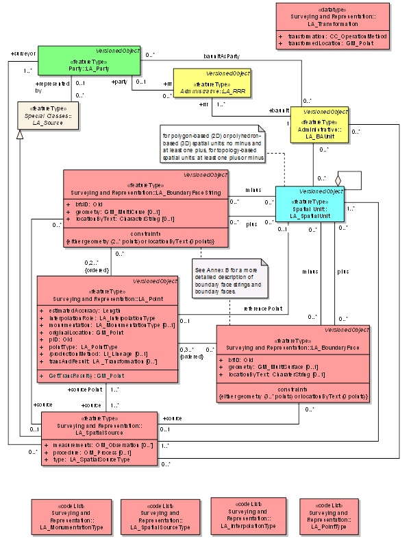
Figure 6. LADM Surveying and Representation Package with
associations to basic classes
Class LA_Point includes the attributes pointIdentifier;
estimatedAccuracy; interpolationRole (this is the role of point in the
structure of a straight line or a curve, e.g. end, isolated, mid,
mid_arc, or start); monumentation (this is the type of monumentation in
the field, e.g. beacon, cornerstone, marker, not_marked);
originalLocation (this is of type GM_Point and concerns the calculated
coordinates from original observations in a Coordinate Reference System
CRS; explained in more detail in Section 4); pointType (e.g. geodetic
control points, or points with or without source documents);
productionMethod; transAndResult (transformation and transformed
location, the transformed location is a new version of the point).
Transformations include for example affine transformations but also
mathematical computations such as least square adjustments. Attribute
GM_Point (ISO 19107:2003, definition 4.61) in class LA_Point is
explained in detail in Section 4 of this paper. Note that there may be 0
or more transAndResult attribute values, implying that there is one (in
orginalLocation) or more (in transAndResult) GM_point value for every
instance of a LA_Point object class.
LA_SpatialSource (as a specialization from LA_Source) contains as
attributes measurements (see Sections 4 and 5), procedure (see Section
4) and LA_SpatialSourceType. LA_SpatialSource is a document providing
facts, for example fieldsketch, GNSS survey, orthophoto, relative
measurement, topographic map, or even video (Barry, 2008). See also
examples in (Lemmen et al, 2010). The document can be used as
authentication for the agreement between neighbors – and also for
reconstruction of boundary points in case of disputes. It may be a
combination of paper (to be scanned later in the offices) and digital
files with observations.
LA_BoundaryFaceString – a boundary is a set of points that represents
the limit of an entity (ISO 19107:2003, definition 4.4). A boundary face
string is a boundary forming part of the outside of a spatial unit.
Boundary face strings are used to represent the boundaries of spatial
units via line strings in 2D. This 2D representation implies in a 2D
Land Administration system a 2D boundary, or in a 3D Land Administration
system a series of vertical boundary faces. In that case an unbounded
volume is assumed, surrounded by boundary faces, which intersect the
earth’s surface (such as traditionally depicted on the cadastral map).
Attributes are: boundaryFacestringId; the geometry (on the ground)
represented via a GM_MultiCurve (note: topology is optional, but not per
se explicitly required, there are alternatives if desired, see Section
3); locationByText (a description of the boundary in words).
LA_BoundaryFace – boundary face: a face that is used in the
3-dimensional representation of a boundary of a spatial unit. Boundary
faces are used when the implied vertical and unbounded faces of a
boundary face string are not sufficient to describe 3D spatial units.
Boundary faces close volumes in height (e.g. every apartment floor), or
in depth (e.g. an underground parking garage), or in all other
directions to form a bounded volume. The volumes represent legal spaces
(in contrast with physical spaces). Attributes are boundaryFaceStringId,
geometry (represented by GMSurface); locationByText (a description of
the face in words).
3. LADM: SPARTIAL UNITS
Spatial units are a flexible concept of representing reality;
different types of spatial units are
supported (Lemmen et al, 2010):
- “sketch based” spatial unit is used when a sketch (a quick draw
of a group of spatial
units) is available; e.g. sketch maps (Törhönen and Goodwin,1998),
and photographs, in the
absence of any better identification. A sketch based spatial unit
can be referred to in
LA_Party attributes (which may an external database) or in
LA_Source.
- “text based” spatial unit is used when the definition of the
spatial unit is entirely by
descriptive text. This includes the “metes and bounds” descriptions.
- “point based” spatial unit is used when the only information
about the location are the
coordinates of a single point within its area (or volume). Jackson
(1996), with references to
several other authors, speaks about the “midpoint concept”. In this
concept the position of a
land right is recorded, not its boundaries. Lester and Teversham
(1995) refer to the concept
as follows: “a single coordinate of the centre of the dwelling unit
could positively identify
that unit, and this may be sufficient for basic recording purposes
where the limits of the
land holding are for the time being unimportant”. This concept is
supported in LADM by
“point based” spatial units. Fourie and Van Gysen (1995) place the
midpoint survey at an
early stage in a system of progressive title improvement, ending in
a standard freehold
system.
- “line-based” (aka “unstructured” or “spaghetti”) spatial unit is
used when the
representation is allowed to have inconsistencies, such as hanging
lines and incomplete
boundaries. This may happen if data are collected over time with
different data acquisition
methods. Referring to Figure 7 it can be seen that, although the
linework is of different
quality and lineage, and in fact does not join in places (the
circled points), a large number
of the parcels are well defined. In fact, to a human user, the
pattern of subdivision is clear.
Different “levels” within the LADM (using the LA_Level class) may be
used for different
qualities.
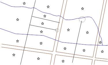
Figure
7. Line based spatial units ,
lines from different sources
- “polygon based” spatial unit (polygon spatial unit) is used when
every spatial unit is recorded as a separate entity. There is no
topological connection between neighboring spatial units (and no
boundaries shared), and so any constraint, enforcing a complete
coverage, shall be applied by the originating and receiving
software.
- “topological based” spatial unit (topological spatial unit) is
used when spatial units share boundary representations. A
topological spatial unit is encoded by reference to its boundaries,
with the common boundary between two spatial units being stored once
only.
Thus there is a topological connection between neighbors.
Finally, 2D and 3D or mixed representations of spatial units are also
possible, see annex E in
ISO 19152 (Lemmen et al, 2010).
4. IMPORTED FUBNCTIONALITY FROM OTHER ISO
STANDARDS
In this section, a number of concepts and classed from other ISO
TC211 standards (as used in LADM) are investigated in more detail; e.g.
GM_Point from ISO 19107, Coordinate Reference Systems from ISO 19111,
OM_Observation from ISO 19165 and DQ_Element from ISO 19115. The class
GM_Point may look simple at first sight, but is it the start of quite a
larger part of the model where relevant cadastral functionality is
available; including support of embedded Coordinate Reference System
(CRS). The GM_Point itself is a type (class) that inherits from the
abstract class GM_Primitive, which in turn inherits from the abstract
class GM_Object; see Figure 8. Out of these three classes only the class
GM_Point has an attribute of type (class) DirectPostion. All three
classes define several (generic) operations. The class DirectPosition
has one attribute called coordinate of type Sequence<Number> and one
derived attribute called dimension of type Integer. Both GM_Object and
DirectPosition have an association to the class SC_CRS (Coordinate
Reference System) as defined in ISO 19111 Referencing by Coordinates;
Both associations have multiplicity 0..1 at the side of SC_CRS.
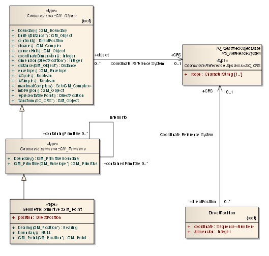
Figure 8. The GM_point (ISO
19107) itself is a type (class) that inherites from the abstract class
GM_Primitive,
which in turn inherits from the abstract class GM_object
The abstract class SC_CRS (Coordinate Reference System) has two
specializations: the classes SC_SingleCRS (again abstract, with several
concrete subclasses; e.g. SC_VerticalCRS, SC_GeodeticCRS,
SC_ProjectedCRS) and SC_CompoundCRS (abstract, an aggreagtion of
SC_SingleCRS); see Figure 9. A SC_SingleCRS is associated with one
CS_CoordinateSystem, which has in turn one or more
CS_CoordinateSystemAxis; see Figure 10. In summary, GM_Point and SC_CRS
are part of a non-trivial model, which should be able to provide all the
functionality needed in the context of LADM and the Survey part:
supporting various coordinate systems and transformations, see Section
6.
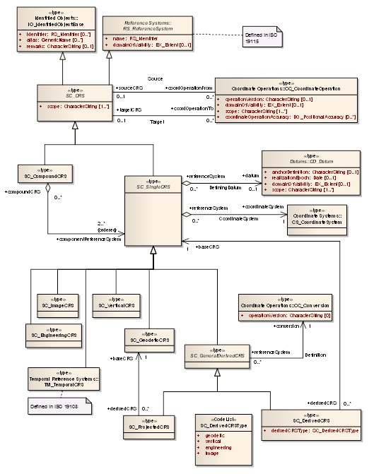
Figure 9.
The abstract class SC_CRS (Coordinate Reference System) From ISO 19111
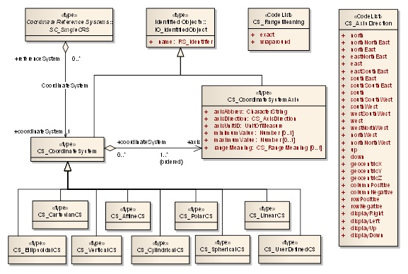
Figure 10. SC_Coordinate System
(from ISO 19111)
Another important ISO/TC211 standard used in LADM is ISO DIS
19156:2010 Observations and Measurements. The survey source data is
modeled and stored in LA_SpatialSource. The attribute “measurements” is
of type OM_Observation (as defined in ISO 19156) and contains the actual
source survey data. The attribute “procedure” is of type OM_Process and
documents the actual survey procedure. The class OM_Observation
contains, in addition to the survey data, also attributes for
documenting the temporal and quality aspects of the survey; see Figure
11.
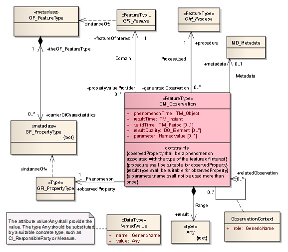
Figure 11.
OM_Observation (from ISO 19156, Note TM_Instant and TM_Period both
from ISO 19108 Temporal Schema)
The class LA_Point inherits of the abstract class VersionedObject.
Besides temporal attributes this also provides attributes for quality
(of type DQ_Element) and source (CI_ResponsibleParty, this is the
responsible organization of a specific instance version in the
database). The quality attribute has multiplicity 0..* and so the
various quality aspects as modelled via DQ_Element can be represented.
DQ_Element is class from ISO 19115:2003 Metadata. It is an abstract
class with the following subclasses: DQ_Completeness,
DQ_LogicalConsistency, DQ_ThematicAccuracy, DQ_Temporal¬Accuracy, and
DQ_PositionalAccuracy; see Figure 12. The source attribute also has
multiplicity 0..* and the class CI_ResponsibleParty is also from ISO
19115:2003 Metadata. Besides a number of names (individual,
organization, positional) also the role and contact information of the
responsible party is modeled; see Figure 13.
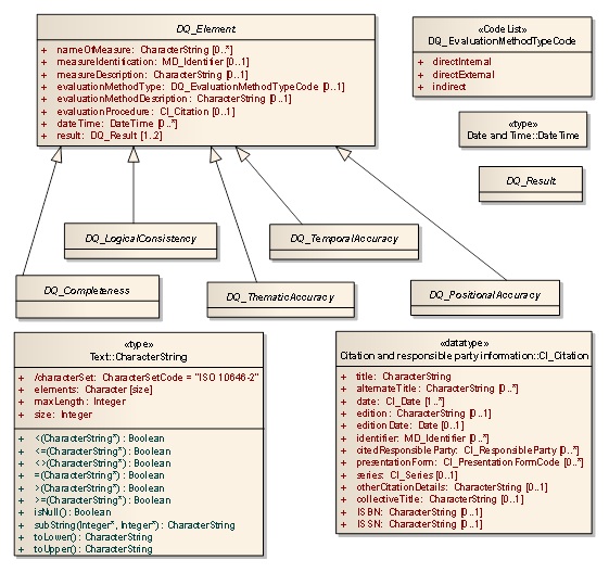
Figure 12. DQ_Element (from ISO 19115)
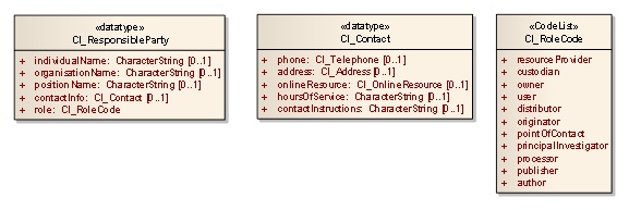
Figure 13. CI_Responsible Party (from ISO 19115)
5. CADASTRAL MAP
A cadastral map represents boundaries of
ownership or land use rights, e.g. customary land rights. Or informal
land rights as possession or occupation. It is in fact a map where it is
(or can be) visualized that people agree on the boundaries of their
properties (or living area’s or environment). From this respect it can
be seen as a social map. It can also be seen as a map representing legal
certainty in relation to ownership or factual land use – which is in
fact also a social issue. The map can be used as a basis for the
calculation of land tax. Again a social issue in relation to the
contribution of individuals, families or groups to building and
maintaining society – of course if organized in a transparent way. An
example of a cadastral map is given in Figure 14. See
http://www.cadastraltemplate.org/fielddata/d2.htm
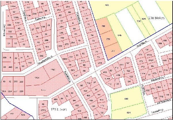
Figure 14. A cadastral map is a social map representing
agreements between people; source of the map is
www.cadastraltemplate.org
Often distinction is made between “general” and “fixed” boundaries,
see (Henssen 1995 and also Bogaerts and Zevenbergen, 2001). Henssen
relates this to data where can be relied on. He states that the English
system mainly relies on physical boundary features, man made or natural.
The precise position of the boundary within these physical features
depends on the “general” land law of the country concerned. This system
is called the “general boundary system”. The LADM also provides,
however, for the precise surveyed boundaries to be “fixed” if desired by
the owners (or other right holders). Inclusion of the survey data in the
Cadastre implies the boundary to be “legally fixed”. In some land
administration systems the location of the boundaries is guaranteed. The
choice between “fixed” and “general” boundaries depends according to
Henssen on the pace of creating or updating the system, the existence of
physical feature, disputes to be expected, the amount of necessary
security and costs. Important observation in the field may be to
identify to whom the physical boundary belongs.
Fixed boundaries are based on surveys in the field. Cadastral
boundary measurements are input for a cadastral mapping process
resulting in coordinates, often published in combination with point
identifiers, bearings (directions or azimuths) and distances between the
points; see Figure 15.
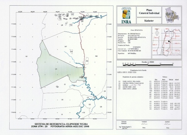
Figure 15. Fixed Boundaries with point identifiers, coordinates,
distances between points and azimuth’s; source INRA, Bolivia
A cadastral map can be seen as a social map as explained above. This
means that land disputes can be visualized in relation to boundaries;
see the example in Figure 16 (courtesy: National Land Centre, Rwanda).
An example map with disputed lands cannot be produced without boundary
observations. A boundary between two spatial units (can be parcels) is
(in principle) to be identified in the field. This is often called
“collecting evidence from the field”. Identification may be very well
possible in a very accurate way in some cases (e.g. with a 10 cm
accuracy). But in many cases this level of accuracy is not possible in
boundary identification. This implies that the precision of
identification of boundary vertexes can be “less accurate” then the
precision of surveys. For this reason (and for reconstruction purposes)
monuments can be placed (beacons, markers, other). Here it should be
noted that monuments can be moved to another place…..
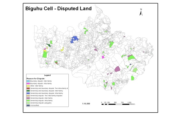
Figure 16. Disputes or overlapping claims on a cadastral map;
source National Land Centre, Rwanda – Field trail period
Apart from surveying (total station, GNSS based surveys etc) it
should be observed that such boundaries may be identified in the field
using areal photo’s, satellite images (Lemmen et al, 2009) or existing
topographic maps. In such cases boundary are drawn using pens or digital
pens. A digital pen “knows” its location on the printed aerial photo or
satellite image because a pattern is printed on the photo which can be
read by the pen. The pen is a device which can be connected to a
computer where super imposition of the drawn boundaries with the image
can be done. Of course it also possible to vectorise directly on top of
the image if both neighbors are represented. Rugema (2011) identified
the advantages of using digital pens for boundary drawing in the field
on top of high resolution ortho photo’s (used as normal for drawing
boundaries in Rwanda): easy for local people in Participatory-Mapping;
boundaries direct georeferenced on site; digital pen predictable for
climate conditions; rechargeable after long time used and no loss of
data when battery is discharged.
Examples of other data acquisition tools are mobile mapping tools, see
for example Lemmens (2010). Most relevant for LADM is not the different
approaches in data acquisition but the options to include the results of
data acquisitions (and processing of those data).
6. CADASTRAL
SURVEYING
The results of cadastral survey projects are measurements with a
certain accuracy (precision) that can be used to describe the geometry
and quality of objects that can be stored in the geo database. The
association between measurements and spatial units is part of the LADM.
In many cases the measurements and observations and their accuracy
(precision) are not stored in the geo database. The quality that can be
derived from the precision of measurements is usually only stored in the
geo database as meta-data about the whole dataset and not per point,
although this information is available from the survey projects results
(Worboys, 1995).
Data collected from surveys and derived coordinates can be managed by
the LADM by using the Surveying and Representation Subpackage. All
documentation related to cadastral boundary surveys can be included in
LADM. Boundary Points or vertexes can be collected in the field by means
of conventional surveys or (hand held) GNSS based systems, etc. Points
can be collected in an office environment (digitizing), or can be
compiled from various sources, for example using forms, field sketches
or orthophotos. Points can be used to compose boundaries
(boundaryFaceStrings). These GM_Points in LA_Point are defined in a CRS
as explained above in Section 4. A SpatialUnit can be 1D, 2D, 3D. Very
common is a 2D cadastre, 3D Cadastres are not common yet but in the
focus of interest in many countries. The dimension of a GM_Point can
also be 3D.
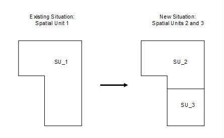
Figure 17. Splitting of a spatial unit (Parcel)
In this section the use of LADM in relation to a classical sub
division of an existing spatial unit is discussed. Before the process
starts this concerns an “existing situation” and a “requested
situation”, when the process is finalized there is an “old” and “new”
situation; where the “new” situation is the up to date “existing”
situation again. See the example case below in Figure 17.
Observations from surveys can be represented in LA_SpatialSource using
the OM_Observations attribute, see Figures 6 and 11. This concerns the
original observations; e.g. GNSS coordinates or, in case of using a
total station: directions, distances, observed control points, etc.
Other observations can be digitized points (e.g. photogrammetric) with
point series, arc series. It should be noted that parallel to,
perpendicular to, collinear to, unit identifiers, object identifiers,
are also observations; even agreement between neighbors on the location
of the boundary belongs to this category. The documents can be
represented in LA_Source using CI_PresentationFormCode attribute. See
Figure 2 for the LA_Source classes. See for an example Figure 18 with
surveyed points and other observations.
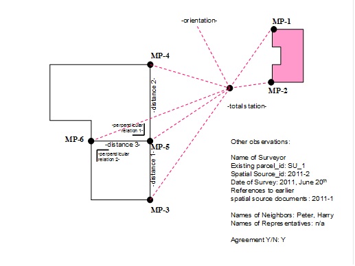
Figure 18 Surveyed points and other observations
The observations are as follows:
Direction and Distance Total Station – MP-1
Direction and Distance Total Station – MP-2
Direction and Distance Total Station – MP-3
Direction and Distance Total Station – MP-4
Direction and Distance Total Station – MP-5
Direction and Distance Total Station – MP-6
Existing X,Y (of building corner in database) of MP-1
Existing X,Y (of building corner in database) of MP-2
Existing X,Y (of spatial unit vertex in database) of MP-4
Existing X,Y (of spatial unit vertex in database) of MP-3
Perpendicular relation 1 (MP-4, MP-5, MP-6)
Perpendicular relation 2 (MP-3, MP-5, MP-6)
Distance 1 between MP-3 and MP-5
Distance 2 between MP-5 and MP-4
Distance 3 between MP-6 and MP-5
MP5 and MP6 to be connected to a boundaryfacestring
MP is Measured Point. In this sample the total station is set up at
an arbitrary location but of course also a set up at a control point or
a total station with integrated GNSS receiver is supported where data
storage in LADM is concerned.
The raw data should be stored together with its quality information
(typically a set of standard deviations). A set of measurements and
observations (geometrical relations and conditions) and control points
will form a network. The network consists of the field data, the control
points and general parameters like dimension of the network, used CRS.
Now the calculation of the coordinates from the observations can be
performed. This implies transformations and/or geodetic adjustments.
Adjustments are needed in case of redundant observations, e.g.
observations related to points observed with a GNSS device which are
also measured using tape. Or points which are observed with total
stations from different setups. In the example above GNSS measurements
are not included.
Least squares adjustments or any other adjustment approach may be used
to compute an optimal solution. This means all observations get
corrections in such a way that the adjusted observations will fit into
the mathematical model. E.g.: in 2D plane geometry the sum of the angles
in a triangle will be equal to 180 deg. This mathematical condition is
generally not valid for the original observations due to (small)
observation errors. The magnitude of the corrections to be applied to
the observations can be used for testing to identify outliers. The least
squares adjustment methodology is a good tool to get an optimal solution
in networks where redundancy exists. The results of the adjustment
process are calculated coordinates which can be represented in LA_Point
under the attribute originalLocation. The transformation parameters can
be represented under transAndResult, see LA_Point in Figure 6.
Having this information available in the geo database a least squares
adjustment engine can at any time be used to re-adjust the network of
observations. It is recommended that the applied least squares engine
uses a sophisticated mathematical model in which (almost) raw
observations can be entered, thus avoiding all kinds of reductions/
corrections which should otherwise be applied in a preprocessing step.
Besides computing final adjusted coordinates it is also important to
check the validity of the available observations via a proven testing
procedure. Most least squares adjustment engines provide a robust data
snooping method which is very useful to identify outliers.
When managing (manipulating, retrieving, analyzing and presenting) the
geographically referenced data in the LADM database, quality information
can be used to interpret the results of the operation. For example, if
one combines two parts of different datasets each containing the same
parcel, but represented by different shapes, quality information may
help to decide which representation is best.
It should be noted that the mathematical method being used for
coordinate determination is independent from LADM, but observations and
the calculated coordinates can be integrated in the LADM. Adjustments
can be reiterated zero or more times (and recorded in the LA_Point
attribute transAndResult of type LA_Transformation, which stores both
the transformation method details and the resulting GM_Point), e.g. when
additional observations become available and/or when additional LADM
control points are included (their coordinates being represented under
LA_BoundaryFaceString). The results of the re-adjustment can be included
in the geometry attribute of LA_BoundaryFaceString.
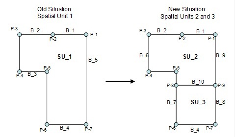
Figure 19 Spatial Unit SU_1 split after survey into SU_2 and SU_3
Now the original observations are stored in LA_SpatialSource, the
originalLocation with calculated coordinates are stored in LA_Point (see
Figure 6) and the adjusted points in boundaries are stored
LA_BoundaryFaceString. The transformation parameters can be kept, as
well as the survey procedure, the estimated accuracy, type of
monumentation in the field, etc. The estimated accuracy of a point can
be derived from the coordinate calculations and from the corrections to
observations in the adjustment calculations. This is a basis for
knowledge about the accuracy of “the map”.
Similar approaches can be used in digitizing existing maps: the original
observations can be stored, the scanned map can be stored, extra
measurements can be included (e.g. related to “roof and ground
situation” in case of photogrammetry) and transformations can be
performed. The subdivision case means the following (in case of a
topological based storage of data); see Figure 19 and 20. Polygons may
be calculated now after subdivision; again this process is not relevant
for LADM, it is important to recognize that the results can be stored.
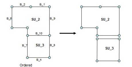
Figure 20 The new spatial units after survey (right: topology
style and left: polygon style)
Calculated area’s can be included into the model now. Again: for the
implementation of LADM it is not important how the management of area
sizes is organized. It is possible to work only with calculated area’s
or with registered and calculated area’s. This means it is useful to
keep the transformation parameters, same for the calculations of
coordinates and the adjustments to the original observations. References
to workflows can be made using attributes as “submission”, “acceptance”
and “recordation” in the LA_Source class. Figures 21 and 22 show the
instance level diagrams with instances of LA_Spatial,
LA_BoundaryFaceString, LA_Point, and LA_SpatialSource related to the sub
division and history management: before and after the split of SU_1 into
SU_2 and SU_3.
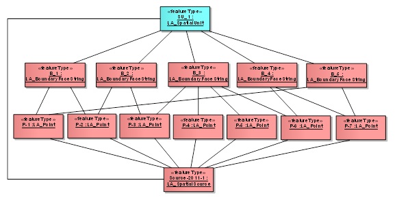
Figure 21 Instance level diagram spatial unit SU_1 before survey
(Source-2011-1 is associated with all boundaries, attribute values of
the object instances not displayed for clarity)
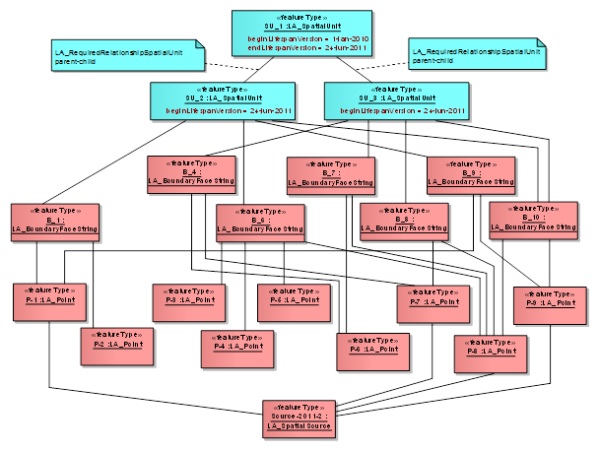
Figure 22 Instance level
diagram with new spatial units SU_2 and SU_3 after survey, SU_1 is now
part of history (Source-2011-2 is also associated with boundaries: B_1,
B_4, B_6, B_7, B_8, B_9 and B_10 and with spatial units SU_2 and SU_3,
this is not depicted)
In LADM timestamps are linked to all contents via LA_VersionedObject;
except to LA_Souce, this means that all data are kept, also after
deletion and eventual introduction of new versions of the data. In other
words: history management is supported. LA_Source are by definition
authentic and can not be changed. Sources from external archives may be
used; e.g. from private surveyor. In the example above the calculated
points P1, P7, P8 and P9 are associated to 2 spatial source documents:
2011-1 and 2011-2. Under 2011-1 there may be 2 versions of points P1
till P9 (first in a local CRS, then in a general CRS). Under 2011-2 P1
and P7 are used for connection of the field observations and those
points do not get a new originalLocation; only a new version because of
the new association with 2011 Source document.
It can be observed in many local cadastral applications in developing
countries that the issue of adjustment of surveys has no or insufficient
attention. Often trials are made to make new observations fitting to the
map by cutting lines or extending lines based on estimations and use of
CAD functions. This is not the most accurate method and this may have
implications on the accuracy of calculated area’s. On the other side we
can see that providers of survey devices include functionalities for on
site adjustments – this may be linked to LADM. The approach as presented
in this chapter may look as a sophisticated approach – but it is normal
surveying.
One more observation is that there will be more and more options for
people in the future to determine boundaries themselves – e.g. using
high resolution images. In some cases extra observations may be needed.
7. CONCLUSIONS
In this paper the surveying and spatial representation subpackage of
the LADM was analyzed in more detail. As this relies on a number if
other ISO TC211 standard, their relevant parts were also analyzed in
order to fully understand the modeling of surveying (and the association
to the spatial units). A typical 2D terrestrial survey was used to
illustrate the capabilities of the LADM in this respect. It is concluded
that the existing LADM was indeed sufficient (both as basic structure,
but also with respect to presented classes and attributes). No
(important) elements had to be added to the model (and are these to be
expected similar in other cases).
In the future additional example cases for alternative spatial data
sources should also be investigated: 3D surveying, ortho photo, and GPS
based measurements. If all fitting within LADM this will show how
generic LADM is. In further investigation we will analyze the use of
exiting types of survey (hardware/software) solutions; e.g. MOVE3,
ESRI‘s Survey Analyst, Trimble, Leica, etc, etc within the context of
the LADM.
Acknowledgements
The authors of this paper would like to express their gratitude to
the ISO 19152 project team members for their contribution to the LADM
standard (in a true team spirit). Special thanks to team member Rod
Thompson for his important contribution w.r.t. the 2D and 3D
(integrated) modelling of LA_SpatialUnits. Also outside the scope of the
project team several persons did have important contributions to the
development of LADM: João P. Hespanha, Jan van Bennekom-Minnema, and
Halil Ibrahim Inan.
References
Barry (2008), Talking Titler Object Manager Manual, Geomatics
Engineering University of Calgary.
Bogaerts, T. and Zevenbergen, J.A. (2001), Cadastral systems:
alternatives. Computers, Environment and Urban Systems, 25 (4-5), pp.
325-337.
Fourie, C. and H. van Gysen (1995). "South Africa just before and just
after the elections:land policies and the cadastre." Geomatica 49(3):
315-328.
Henssen, J.L.G. (1995). “Basic principles of the main cadastral systems
in the world”. In Proceedings of the One Day Seminar of the FIG Working
Group Cadastre 2014, held during the Annual Meeting of Commission 7,
Cadastre and Rural Land Management, of the International Federation of
Surveyors (FIG), May 16, Delft, The Netherlands.
ISO, CEN TC287 /WG 3, 2009. Geographic information – Land Administration
Domain Model. Technical Report draft of ISO 19152 (N1360), International
Organization for Standardization, 2009.
ISO (2011). ISO/DIS 19152. Draft International Standard (DIS).
Geographic information - Land administration domain model (LADM).
Geneva, Switzerland, ISO: 110p.
Jackson, J. (1996). "Extending the South African cadastral system using
a mid-point method." South African Journal of Surveying and Mapping
23(5): 277-284.
Kaufmann, J., Steudler D., 1998. Cadastre 2014. A vision for a future
cadastral system. FIG-Commission 7, Brighton, U.K.
Lemmen, C. H. J., J. A. Zevenbergen, M. Lengoiboni, K. Deininger and T.
Burns (2009). First experiences with high resolution imagery based
adjudication approach in Ethiopia. The World Bank Annual Bank Conference
on Land Policy and Administration. Washington, D.C.
Lemmen, Ch., Van Oosterom, P., Thompson, R., Hespanha, J., Uitermark, H.
(2010). The modelling of spatial units (parcels) in the Land
Administration Domain Model (LADM). FIG Conference 2010. Sydney,
Australia, FIG.
Lemmen, Christiaan, The Social Tenure Domain Model, FIG, 2010.
Lemmens, Mattias, (2010), Mobile GIS Systems, GIM International,
December 2010, Volume 24, Number 12.
Lester, K. J. and J. Teversham (1995). "An overview of the cadastral
system in South Africa." South African Journal of Surveying and Mapping
23(2): 103-114.
Milindi Rugema, D. (2011) Evaluation of digital pen in data capturing
for land administration purposes in Rwanda. Enschede, University of
Twente Faculty of Geo-Information and Earth Observation ITC, 2011.
Törhönen, M.-P. and D. P. Goodwin (1998). "Would a registry map hang
comfortably in a round mud hut? A register of title for Zimbabwe’s
communal areas: philosophical and technical considerations." Australian
Surveyor 43(2).
Worboys, M.F., GIS: A Computing Perspective, Taylor&Francis, 1995.
BIOGRAPHICAL NOTES
Peter van Oosterom obtained an MSc in Technical Computer Science in
1985 from Delft University of Technology, The Netherlands. In 1990 he
received a PhD from Leiden University for this thesis ‘Reactive Data
Structures for GIS’. From 1985 until 1995 he worked at the TNO-FEL
laboratory in The Hague, The Netherlands as a computer scientist. From
1995 until 2000 he was senior information manager at the Dutch Cadastre.
Since 2000, he is professor at the Delft University of Technology (OTB
institute) and head of the section ‘GIS Technology’. He is the current
chair of the FIG joint commission 3 and 7 working group on
‘3D-Cadastres’ (2010-2014).
Christiaan Lemmen holds a degree in geodesy from Delft University of
Technology, The Netherlands. He is an assistant professor at the Faculty
of Geo-Information Science and Earth Observation (ITC), University of
Twente, and an international consultant at Kadaster International. He is
chair of the Working Group 7.1 ‘Pro Poor Land Management’ of FIG
Commission 7, ‘Cadastre and Land Management’, and contributing editor of
GIM International. He is director of the FIG International Bureau of
Land Records and Cadastre OICRF.
Harry Uitermark holds a degree in geodesy from Delft University of
Technology, The Netherlands, and received a PhD for his research on
‘Ontology-based geographic data set integration’ in 2001 from the
University of Twente, The Netherlands. He worked many years with the
Dutch Cadastre, and has been a visiting scientist at the Faculty of
Geo-Information Science and Earth Observation (ITC), University of
Twente.
CONTACTS
Prof. Dr. Peter van Oosterom
Delft University of Technology
OTB, Section GIS-technology
P.O. Box 5030
2600 GA Delft
THE NETHERLANDS
Tel. +31 15 2786950
E-mail:
P.J.M.vanOosterom@tudelft.nl
website http://www.gdmc.nl
Christiaan Lemmen
Netherlands Cadastre, Land Registry and Mapping Agency
P.O. Box 9046
7300 GH Apeldoorn
E-mail: Chrit.Lemmen@kadaster.nl
University of Twente. Faculty of Geo-Information Science and Earth
Observation (ITC)
P.O. Box 6
7500 AA Enschede
THE NETHERLANDS
E-mail:
chrit.lemmen@kadaster.nl
Dr. Harry Uitermark
Rietveldstraat 20
7425 EL Deventer
THE NETHERLANDS
E-mail:
harry.uitermark@planet.nl
 |